|
Stanton Scattering Lab
Virtual Tour
|
|
|
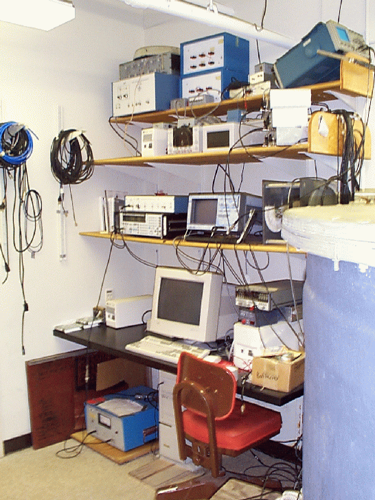 Main Lab Setup Main Lab Setup |
This is our basic lab setup. All the equipment necessary for processing is
located here.
It all starts here in our computer. It's a Pentium 166, 32M RAM, 7G of hard drive, a Jaz drive, and a CD-R burner. However the important part of the computer is the fact that it talks to our other equipment through a GP-IB interface. |
|
Our experiments begin with the Analogic Polynomial Waveform Generator. (the bottom machine) It produces the shape, duration, and frequency characteristics of the waves that will be scattered. The waveforms can be programmed through the keypad, or they can be inputted in the computer and sent over the GPIB.
| 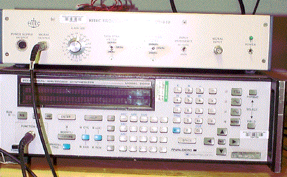
Waveform Generator (bottom box) |
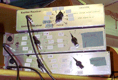 Switching Boxes Switching Boxes |
Once the waveform is selected, it is sent to the ENI power amp. This is a 100 Watt amplifier with a broadband spectrum (10 kHz - 12 Mhz). After the signal is amplified it goes to our switching boxes which control what transducer the signal is sent to. We also take a -40 dB tap off of the amplified signal and put that on one of our oscilloscopes channels to view and record. |
|
Once the desired transducer is selected, the signal goes to the transducer which transforms the electrical signal into an underwater pressure signal. It travels through the water column, and then is scattered. Our system is normally setup to record backscattered energy ( energy that is reflected back towards the source. We normally use this array, which contains 2 transducers (one transmits the signal, the other receives it) for 12 different frequencies. |
Center Frequency & Bandwidth
24 kHz Narrowband
50 kHz Narrowband
75 kHz Narrowband
120 kHz Narrowband
200 kHz Narrowband
250 kHz Broadband
500 kHz Narrowband
500 kHz Broadband
1 MHz Narrowband
1 MHz Broadband
2 Mhz Narrowband
|
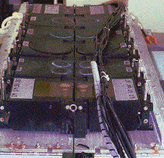 Ducer Array Ducer Array |
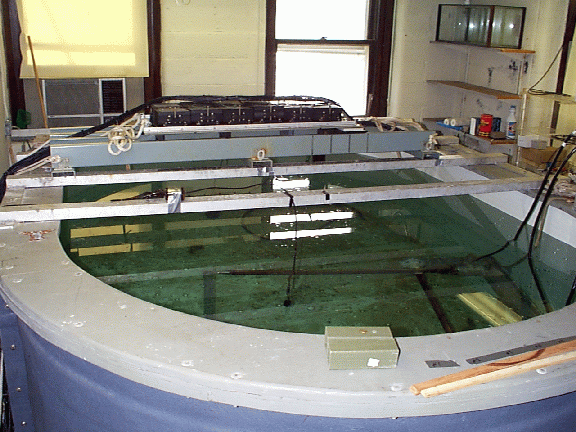 Experiment Tank Experiment Tank |
The transducer array is placed in a large fiberglass seawater tank. Water for experiments is filtered and pumped in from Vineyard Sound (which is just outside the lab's window). The tank dimensions are approximately 6' diameter (major axis), 4' diameter (minor axis) and 5' high. It holds a lot of water. |
|
The tank has several beams going across the top to enable the experimenter to look at the scatterer and the transducer array during the course of an experiment. These beams also allow us to mount a stepper motor that can then rotate the scatterer in increments as small as 1 degree. | 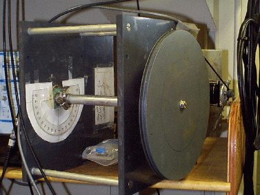 Stepper Motor Stepper Motor |

Ritec Amp/Filter (top box) |
Once the sound is scattered, the backscattered pressure wave hits the recieve transducer and is converted back to an electrical signal. The signal passes through the switch box and is then run through a battery operated Ultrasonic Pre-amp. From there it enters a Ritec BR-640 which is a combination amplifier and filter. (the eggshell colored boxes here) |
| Once the signal is filtered and amplified it is sent to our 10 bit 150 MHz LeCroy Oscilloscope. A tap from this signal is sent to a Textronix oscilloscope that is mounted above the tank such that one can see the backscattered signal while they are on top of the tank adjusting the animal and/or the transducers.
The LeCroy Oscilloscope can store and average many returns internally, thus we are able to store a background noise signal on the scope and subtract that from the echo on-the-fly. The signal is then sent to the computer through the GPIB bus and is written to the hard drive. | 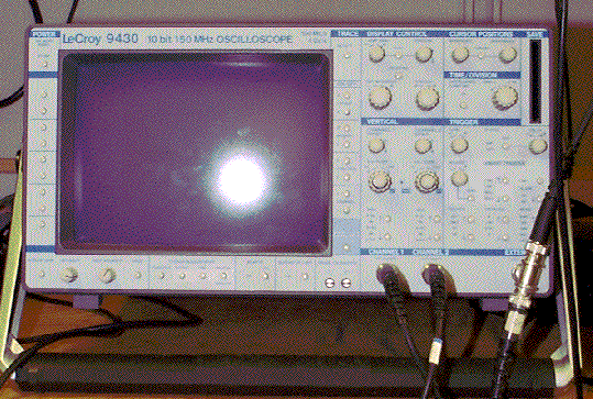
LeCroy Scope |
An integral part of the lab is the data acquisition software which is a custom program written in Visual Basic by Bob Eastwood and revised by Dezhang Chu. It has a GUI interface allowing the user to select the number of pings, what frequency transducer to use, whether or not to use the stepper motor, and several other features.
We hope you've enjoyed your virtual visit to Bigelow G-8, and that you now have a better understanding of the science that can be performed here. If you are interested in using our facilities for an experiment, please contact us.
|
Last updated: July 26, 2011
|